





Last Updated 2 hours ago by Kenya Engineer
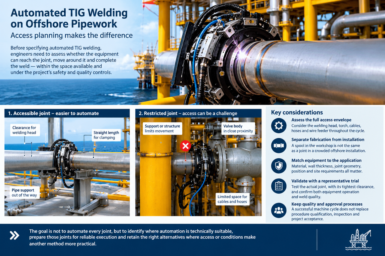
Pipework installation presents a challenge that extends beyond selecting the appropriate welding process. On an offshore platform, a circumferential pipe joint may be positioned beside a structural support, beneath a deck or within a crowded service corridor. The available space can determine whether automated welding equipment can be fitted, operated and removed without disturbing neighbouring components.
This creates a planning issue for engineers responsible for piping design, fabrication and installation. A welding head may accommodate the outside diameter of a pipe and still be unsuitable for a particular joint because the surrounding geometry prevents it from completing the required movement.
Automated tungsten inert gas (TIG) welding can offer repeatable control over welding parameters and torch movement. Its practical application, however, depends on the relationship between equipment configuration, joint preparation, material requirements and access at the point of installation.
For offshore projects, these considerations are best addressed during design and fabrication planning rather than after pipework has been installed.
Workshop fabrication and installed pipework present different challenges
A pipe spool fabricated in a workshop can be positioned to provide access around its joints. Fabricators can rotate the assembly, reposition fixtures and select a welding sequence that accommodates the equipment. The completed spool can then be transported to site for installation.
The situation changes when a joint must be welded in its final position. Nearby valves, flanges, pipe branches, supports and structural members may restrict the space available for mounting a welding head. The operator may also have limited visibility of the joint and little room to manage the equipment’s power cables, cooling lines or shielding-gas connections.
The critical measurement is consequently not the clearance at the starting point alone. Engineers need to consider the full operating envelope of the equipment, including the space required to attach the head, complete the welding cycle and remove it afterwards.
Pipe bends, tees and closely spaced fittings deserve particular attention because they can limit the straight length available for clamping and positioning. The minimum clearance required varies with the equipment design and the joint configuration.
These constraints can be identified from piping isometric drawings and three-dimensional models, but a drawing review may not capture every obstruction encountered during installation. A physical mock-up or representative trial can help establish whether the proposed arrangement is workable.
Where access is inadequate, the options may include changing the fabrication sequence, completing the joint before installation, modifying the approved arrangement or selecting another suitable welding method. Any alteration affecting structural integrity, piping design or operational safety must follow the project’s engineering approval process.
Equipment capability must match the welding application
Automated TIG welding systems are available in configurations intended for different pipe diameters, wall thicknesses and joint arrangements. The selection process must account for the actual application rather than relying on a machine’s headline operating range.
Material grade, wall thickness, joint preparation, welding position and the applicable welding procedure all influence whether a particular system is suitable. The available pipe length and space around the joint also determine whether its welding head can be mounted and operated as intended.
Electrical supply and cooling requirements need similar attention. A machine’s rated current range does not establish the parameters required for a particular weld, while an advertised cooling arrangement does not demonstrate that the equipment is suitable for every site environment.
Offshore installations introduce further requirements. Equipment intended for use in a hazardous area must meet the applicable site requirements and have the necessary approvals for its intended location. A general industrial rating should not be treated as evidence of hazardous-area suitability.
The choice of welding process must also remain separate from the assessment of physical access. An installation may provide enough room for a welding head yet still present difficulties with fit-up, alignment, heat input or maintaining the required welding conditions.
Automated operation controls aspects of weld execution, but it does not correct poor joint preparation or guarantee acceptable weld quality. Those outcomes depend on the complete welding system, including the procedure, equipment setup, consumables, operator competence and inspection arrangements.
Welding quality requires more than a successful machine cycle
A welding head completing a full circuit around a pipe demonstrates that the equipment can perform the programmed movement. It does not, on its own, establish that the resulting weld meets the project’s acceptance requirements.
Joint preparation and fit-up remain critical. Variations in root gap, alignment and groove geometry can affect penetration and fusion. The welding procedure must define the permitted parameters and the conditions under which the joint is to be produced.
Before production begins, the proposed arrangement should be demonstrated using representative materials, dimensions, joint preparation and welding positions. Where restricted access is the principal concern, the trial should reproduce the obstruction that creates the tightest clearance. Testing an unobstructed sample may establish basic machine functionality without resolving the actual installation problem.
The demonstration should assess more than equipment movement. It should confirm that the head can be installed and removed, connections remain clear throughout the cycle, the joint can be prepared as required and the resulting weld can be inspected using the specified methods.
The applicable welding procedure qualification, production controls and inspection requirements must also be established. Depending on the service and governing specification, these may include visual examination and non-destructive testing.
Responsibility for approving the welding procedure, reviewing inspection results and authorising the joint for service must remain clearly assigned. A successful demonstration does not replace these requirements.
Designing for fabrication can reduce site constraints
Access planning is particularly valuable when engineers can influence the piping arrangement before fabrication begins. Moving a joint to a more accessible position or completing a weld in the workshop may avoid the need to introduce specialised equipment into a congested installation.
Such decisions should be evaluated alongside transport limitations, lifting arrangements, installation sequence and the need to connect the completed pipework to existing systems. Moving a joint to improve welding access may create a different constraint elsewhere, making coordination between piping designers, fabricators and installation teams essential.
A practical review should identify joints that can be completed under controlled workshop conditions, those suitable for automated welding after installation and those likely to require an alternative method. This allows equipment selection and welding procedures to be developed around the planned work rather than adjusted at the last minute.
For projects involving extensive repetitive pipework, early planning can also improve consistency in equipment setup and inspection. The benefits depend on the proportion of joints suitable for the selected process, the time required to configure the equipment and the cost of addressing access restrictions during installation.
An engineering decision made before mobilisation
Automated TIG welding should be assessed as part of the overall piping and fabrication strategy. The central question is whether the proposed equipment can execute the approved welding procedure on the specified joint, in its intended position, within the available space and under the project’s safety and quality controls.
Answering that question requires coordination between design, fabrication, welding engineering and inspection personnel. It also requires a realistic demonstration where drawings alone cannot establish that the equipment will fit and operate as intended.
On offshore installations, where access can be constrained by surrounding structures and interconnected services, the timing of that assessment is important. Resolving the issue before mobilisation gives project teams more options than discovering the limitation after the pipework is in place.
The objective is not to automate every joint. It is to identify where automation is technically suitable, prepare those joints for reliable execution and retain appropriate alternatives where the geometry or site conditions make another method more practical.
-
Product on sale
 AWEBook Volume 2Original price was: KShs 3,500.00.KShs 3,000.00Current price is: KShs 3,000.00.















 welding can offer repeatable control over welding parameters and torch movement)