Last Updated 4 hours ago by Kenya Engineer
A borehole near the Tanzania–Kenya border produced water containing 6.9 mg/L of fluoride, 3.49 mg/L of iron and nearly 1,800 mg/L of total dissolved solids. A reverse osmosis plant designed to treat this water illustrates why effective iron removal, scaling control and responsible management of treatment waste are essential to successful groundwater treatment.
Groundwater along the East African Rift Valley and its volcanic highlands can contain elevated concentrations of naturally occurring fluoride, alongside iron, dissolved salts and microbiological contaminants. The region is among the world’s well-documented high-fluoride groundwater zones [3].
Reverse osmosis (RO) offers an effective treatment option for many of these water-quality challenges. However, its performance depends heavily on appropriate pretreatment, membrane protection, recovery-rate selection and a suitable method of disposing of the concentrated reject stream.
This article examines a 5 m³/h reverse osmosis plant designed for a borehole in Tanzania’s Kilimanjaro border region, close to Kenya. The system was designed and manufactured by Guangzhou GlobalUF Water Treatment Co., Ltd., factory-tested and shipped to the project site. At the time of writing, the owner was undertaking installation and commissioning.
An important qualification is that the factory test was conducted in June 2026 using low-salinity municipal water in Guangzhou. It was not a performance test using the actual borehole water. The water-quality figures presented here are from a laboratory analysis conducted in March 2024, while the treatment specifications represent the plant’s design.
Drinking-water standards and treatment targets
The World Health Organization (WHO) recommends a guideline value of 1.5 mg/L for fluoride in drinking water [1, 2]. The East African potable-water specification, adopted in Kenya as KS EAS 12:2018, sets the same fluoride limit. It also specifies maximum concentrations of 0.3 mg/L for iron, 0.1 mg/L for manganese and 200 mg/L for sodium [4].
Although WHO does not establish a health-based guideline value for total dissolved solids (TDS), it notes that water containing less than approximately 600 mg/L is generally palatable. Palatability tends to decline as concentrations exceed 1,000 mg/L [1].
These benchmarks provide a useful basis for assessing the raw borehole water and determining the treatment requirements.
Understanding the borehole water quality
Laboratory analysis conducted in March 2024 identified several parameters requiring attention before the water could be considered suitable for drinking.
Fluoride was measured at 6.9 mg/L, more than four times the WHO guideline value. Iron was 3.49 mg/L, substantially above the KS EAS 12 limit of 0.3 mg/L. Total dissolved solids stood at 1,778 mg/L, while sodium was recorded at 500 mg/L.
The sample also contained turbidity of 10 NTU, colour of 64 Pt-Co and high bacterial counts. These findings indicate that treatment would need to address both dissolved contaminants and suspended or microbiological impurities.
The pH was 7.48, within the normal drinking-water range. Total hardness was 176 mg/L as CaCO₃, a moderate level that is below the 300 mg/L limit specified for treated water under KS EAS 12 [4].
One particularly important characteristic was the reported total alkalinity of 1,014 mg/L as CaCO₃. The laboratory also reported bicarbonates at 1,014 mg/L as HCO₃⁻. These are different chemical expressions and are not directly equivalent. The scaling assessment discussed in this article uses the reported alkalinity value expressed as CaCO₃.
The complete laboratory results are presented in Table 1.
Managing scaling risks at 60% recovery
A major consideration in designing the RO system was the potential for mineral scaling, particularly calcium carbonate precipitation.
The plant was designed to operate at 60% recovery. This means that approximately 60% of the incoming feed water becomes treated product water, while the remaining 40% leaves the system as concentrate.
At this recovery rate, the concentration factor is:
Concentration factor = 1 ÷ (1 − 0.60) = 2.5
Consequently, substances rejected by the membranes, including calcium, bicarbonate, fluoride, sodium and silica, can become approximately 2.5 times more concentrated in the reject stream.
The high bicarbonate alkalinity is particularly important. Despite the relatively moderate hardness and normal raw-water pH, the combination of calcium and high alkalinity creates a significant calcium carbonate scaling risk.
A standard Langelier Saturation Index assessment, using the reported pH, calcium and alkalinity at ordinary ambient temperature, indicates a positive saturation index in the raw water. The risk increases further as water becomes concentrated through the RO system.
Silica also requires attention. At a concentration factor of 2.5, the projected silica concentration in the concentrate would be approximately 125 mg/L.
The treatment design does not include acid dosing or a water softener. Instead, scaling is managed through the selected 60% recovery rate and the application of a scale inhibitor before the RO membranes. The inhibitor selection should be supported by a supplier’s projection based on the actual water chemistry rather than assumptions based on hardness alone.
The treatment process and equipment configuration
The treatment train was adjusted during the design process to improve the handling of iron and suspended impurities before water reaches the RO membranes.
Raw water is collected in a 10 m³ tank supplied by the project owner. The same tank serves as the reaction and aeration vessel. A blower rated at 5 m³/h and 0.75 kW supplies air to the tank.
Three chemicals are introduced through metering pumps and silicone hoses positioned at the bottom of the tank:
- Sodium hydroxide (NaOH), which raises the pH and supports the oxidation of ferrous iron.
- Polyaluminium chloride (PAC), which acts as a coagulant to assist the aggregation of suspended particles.
- Sodium hypochlorite (NaClO), which provides oxidation and disinfection.
The combination of chemical dosing and aeration is intended to improve the oxidation of dissolved ferrous iron (Fe²⁺) and encourage the settling of some suspended impurities.
This arrangement represents an adjustment from the original process drawing, which placed the flocculant and biocide dosing points at the iron-filter inlet. Moving the dosing points to the reaction tank allows more contact time before filtration.
A raw-water transfer pump rated at 10 m³/h, 35 m head and 1.5 kW then supplies the filtration section.
Iron removal and filtration
Three media filters, each measuring 1,000 mm in diameter and 2,100 mm in height, are installed in series. Each is rated at 8.5 m³/h.
The filtration sequence comprises:
1. Manganese sand filter
The first filter contains manganese sand, based on manganese dioxide media. Its primary purpose is to remove oxidised iron and reduce manganese concentrations. The design aims to reduce the iron concentration from the original 3.49 mg/L towards the 0.05 mg/L ferric-iron level referenced in typical membrane feed-water guidelines [6].
2. Sand filter
The second filter provides additional removal of suspended particles and residual turbidity. It also contributes to lowering the silt density index (SDI), an important indicator of the potential for particulate fouling of RO membranes.
3. Activated carbon filter
The third filter removes residual chlorine introduced through sodium hypochlorite dosing. This is particularly important because the polyamide membranes commonly used in RO systems are vulnerable to oxidising agents.
Membrane manufacturers generally specify a maximum free chlorine concentration of 0.1 mg/L or less at the membrane inlet [6]. Activated carbon also assists in reducing colour and certain organic compounds.
Following the media filters, a reducing agent is dosed as an additional safeguard against residual chlorine. A scale inhibitor is also introduced before the cartridge filtration stage.
A 5 µm cartridge filter, rated at 10 m³/h, provides the final particulate barrier before water enters the RO system.
Reverse osmosis and treated-water storage
The plant uses a brackish-water reverse osmosis configuration designed for approximately 60% recovery.
At a feed flow of approximately 8.3 m³/h, the expected treated-water production is 5.0 m³/h.
The high-pressure pump is rated at 10 m³/h, 130 m head (approximately 13 bar) and 5.5 kW.
After passing through the RO membranes, the treated water undergoes ultraviolet disinfection before being transferred to a 5 m³ product-water storage tank supplied by the owner.
The system also includes a clean-in-place (CIP) assembly comprising a 300-litre cleaning tank and a pump rated at 10 m³/h and 1.5 kW. This equipment allows chemical cleaning of the membrane system when required.
The installed configuration does not include a remineralisation unit or a blending line.
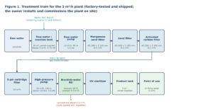
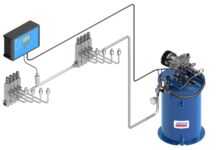
Figure 1. Treatment train for the 5 m³/h RO plant, showing the raw-water reaction tank, chemical dosing and aeration, three-stage media filtration, cartridge filtration, reverse osmosis, ultraviolet disinfection and product-water storage. Diagram: GlobalUF.
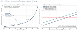
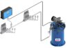
Figure 2. (a) At 60 % recovery the concentrate is 2.5 times as strong as the feed; if fluoride rejection is high, concentrate fluoride is about 17 mg/L from a 6.9 mg/L feed. (b) Blending, if used, is limited by fluoride. This plant has no blending line; panel (b) is an option, not part of the installed train. Example permeate values are illustrative only. (Diagram: GlobalUF)
What factory testing establishes and what it cannot prove
The RO skid underwent factory testing in Guangzhou in June 2026 before shipment.
During the test, the conductivity meter recorded approximately 259 µS/cm on the feed side and 9.09 µS/cm on the permeate side.
This corresponds to an apparent salt rejection of approximately 96.5%.
The results demonstrate that the membrane elements and associated instruments were functioning during the factory test using the available low-salinity municipal water.
However, these figures should not be interpreted as evidence of the plant’s performance on the project borehole.
The actual borehole water has a conductivity of 2,830 µS/cm, compared with approximately 259 µS/cm in the factory test. It also contains elevated fluoride and iron concentrations that were not represented by the factory test water.
Factory testing can establish important aspects of the equipment’s construction and operation, including hydraulic performance, control interlocks, flow rates and the operation of the skid under test conditions.
It cannot, by itself, establish the effectiveness of iron removal, fluoride rejection or antiscalant performance under the actual borehole chemistry.
Site commissioning will therefore be essential. Measurements should include iron and turbidity at the outlets of the individual filters, SDI at the RO inlet, and fluoride, TDS, sodium, iron and bacterial levels in the treated water.
Typical membrane feed-water guidelines recommend turbidity below 1 NTU, an SDI below 5 (preferably below 3) and very low ferric iron concentrations [6].
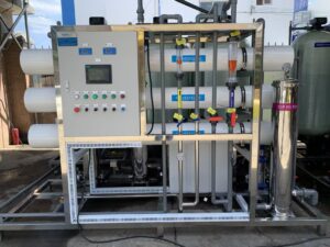
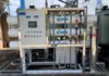
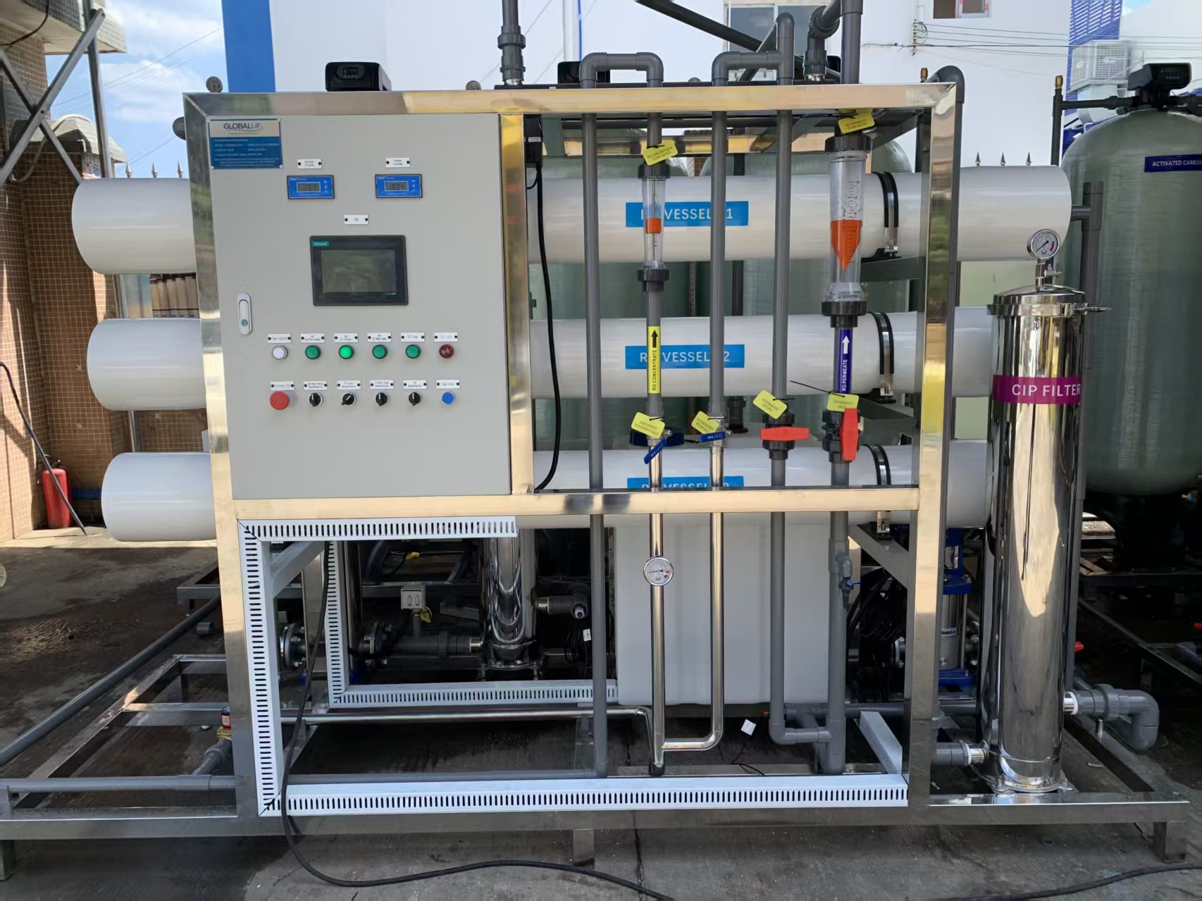
Figure 3. The 5 m³/h brackish-water RO skid during a factory water test in Guangzhou, China, in June 2026, before shipment. This is a factory photograph, not an image from the project site. Photo: GlobalUF.
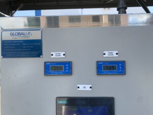
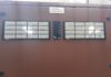
Figure 4. Conductivity readings recorded during the Guangzhou factory test, showing approximately 259 µS/cm on the feed side and 9.09 µS/cm on the permeate side. The test used low-salinity municipal water rather than the project borehole water. The 4 kW figure visible on the equipment nameplate does not represent the complete plant’s installed power, which is 7.5 kW according to the process drawing. Photo: GlobalUF.
Managing the RO concentrate and environmental implications
An important aspect of groundwater treatment that is sometimes overlooked is the management of the concentrated reject stream.
At 60% recovery, approximately 40% of the incoming feed water leaves the RO system as concentrate. For this installation, the expected reject flow is approximately 3.3 m³/h.
Because the membranes reject a substantial proportion of dissolved salts and other contaminants, the concentrate contains higher concentrations of these substances than the incoming water.
Fluoride is particularly significant in this case. Assuming high fluoride rejection by the membranes, most of the fluoride entering the plant will be retained in the concentrate.
At 60% recovery, the projected concentration factor is 2.5. A feed concentration of 6.9 mg/L could therefore produce a concentrate containing approximately:
6.9 ÷ 0.40 = 17.25 mg/L fluoride
This is a design projection based on high fluoride rejection, not a measured result from the installation.
The environmental implications are significant. In Kenya, discharge into the environment is regulated by the National Environment Management Authority (NEMA) under the Water Quality Regulations, which include a fluoride limit of 1.5 mg/L [5].
On the Tanzanian side of the border, the project must also comply with the applicable environmental requirements.
A concentrate stream potentially containing approximately 17 mg/L fluoride should not be discharged indiscriminately into surface water or directed into an ordinary soakaway.
An approved disposal or management arrangement must be established as part of the project design. A properly designed and lined evaporation pond is one possible option, subject to the applicable environmental approvals and site conditions.
The reject stream should be treated as an integral part of the water-treatment design, rather than as an afterthought once the RO equipment has been installed.
Product-water quality, remineralisation and blending
The expected fluoride concentration in the treated water depends on membrane rejection performance under the actual operating conditions, including feed-water chemistry, pH and temperature.
Brackish-water polyamide membranes can achieve high fluoride rejection, and the design expectation is that the system can reduce the incoming fluoride concentration sufficiently to meet the 1.5 mg/L guideline.
However, this must be confirmed through the manufacturer’s membrane projection and, ultimately, laboratory testing during site commissioning. No borehole-based fluoride rejection result is available from the factory test.
Following RO treatment, remineralisation may also be considered. One possible approach is a calcite contactor, which can introduce calcium and alkalinity into the treated water and improve its mineral balance [7, 8].
Blending treated water with a proportion of pretreated raw water is another possible approach, although the high fluoride concentration in the original borehole water places strict limits on how much raw water can be introduced without exceeding the drinking-water guideline.
Neither remineralisation nor blending is included in the current plant configuration. Any decision to introduce these processes would need to be evaluated against the required final water quality.
Power requirements, operation and maintenance
The complete plant has an installed power supply requirement of 7.5 kW, operating at 400 V, three-phase and 50 Hz.
The principal electrical loads shown on the process drawing are:
- Aeration blower: 0.75 kW.
- Raw-water transfer pump: 1.5 kW.
- RO high-pressure pump: 5.5 kW.
The high-pressure pump accounts for the largest share of the installed power requirement.
Based on a pumping pressure of approximately 13 bar, an assumed pump efficiency of 70% and 60% recovery, the estimated energy consumption of the high-pressure pumping stage is approximately 0.9 kWh per cubic metre of product water. This estimate excludes the blower, raw-water pump, controls and other auxiliary equipment.
Proper shutdown procedures are equally important. Every shutdown, including one caused by a power failure, should be followed by a low-pressure flushing cycle, preferably using permeate water, in accordance with membrane manufacturers’ recommendations [6, 9].
Routine operation should include recording operating pressures, feed and permeate flows, and conductivity readings. Media filters require regular backwashing, while cartridge filters and chemical dosing systems must be maintained according to operating requirements.
Local availability of chemicals, replacement cartridges and essential spare parts is also important in ensuring continuity of operation.
At least two people at the installation should receive practical training in system operation, routine maintenance, troubleshooting and emergency shutdown procedures.
Conclusion
Treating high-fluoride, iron-rich and brackish groundwater requires more than selecting an RO membrane with an appropriate capacity.
The 5 m³/h installation in Tanzania’s Kilimanjaro border region illustrates the importance of understanding the complete water chemistry before designing a treatment system.
High iron concentrations require effective oxidation and filtration before the water reaches the membranes. High bicarbonate alkalinity and silica require careful scaling projections at the intended recovery rate. Residual chlorine must be removed to protect the polyamide membranes, while the concentrated reject stream requires an environmentally acceptable disposal arrangement.
Equally important is the distinction between factory performance and actual site performance. Final water quality must be established through commissioning tests using the borehole water itself.
For projects involving challenging groundwater conditions across East Africa, successful RO treatment depends on a coordinated approach that brings together laboratory analysis, appropriate pretreatment, membrane selection, scaling control, concentrate management and properly trained local operators.
Table 1. Borehole water analysis (March 2024) and drinking-water limits
| Parameter | Laboratory result | Reference limit or guideline |
|---|---|---|
| pH | 7.48 | 6.5–8.5 |
| Total dissolved solids (TDS) | 1,778 mg/L | Palatability generally declines above 1,000 mg/L |
| Electrical conductivity | 2,830 µS/cm | — |
| Turbidity | 10 NTU | — |
| Colour | 64 Pt-Co | — |
| Iron | 3.49 mg/L | 0.3 mg/L |
| Manganese | 0.06 mg/L | 0.1 mg/L |
| Fluoride | 6.9 mg/L | 1.5 mg/L |
| Sodium | 500 mg/L | 200 mg/L |
| Calcium | 61 mg/L | — |
| Magnesium | 6 mg/L | — |
| Total hardness | 176 mg/L as CaCO₃ | 300 mg/L (treated water) |
| Total alkalinity | 1,014 mg/L as CaCO₃ | — |
| Bicarbonates | 1,014 mg/L as HCO₃⁻ | — |
| Sulphate | 110 mg/L | — |
| Chloride | 50 mg/L | — |
| Silica | 50 mg/L as SiO₂ | — |
| Nitrate | 9 mg/L as NO₃⁻ | — |
| Total coliforms, E. coli and total viable count | Too numerous to count | Not detectable / very low |
Sources: WHO Guidelines for Drinking-water Quality [1, 2] and KS EAS 12:2018 [4]. A dash indicates that a corresponding limit was not specified in the original laboratory comparison.
References
- World Health Organization (WHO). 2022. Guidelines for Drinking-water Quality: Fourth Edition Incorporating the First and Second Addenda. Geneva: WHO.
- World Health Organization (WHO). 2022. ‘Fluoride.’ Chemical fact sheet in Guidelines for Drinking-water Quality: Fourth Edition Incorporating the First and Second Addenda. Geneva: WHO.
- Fawell, J., K. Bailey, J. Chilton, E. Dahi, L. Fewtrell and Y. Magara. 2006. Fluoride in Drinking-water. London: IWA Publishing, on behalf of the World Health Organization.
- Kenya Bureau of Standards (KEBS). 2018. KS EAS 12:2018 Potable Water – Specification. Nairobi: KEBS.
- Republic of Kenya. 2006. The Environmental Management and Co-ordination (Water Quality) Regulations, Legal Notice No. 120 of 2006, Third Schedule. Nairobi: Kenya Law. Current regulatory requirements should be confirmed with NEMA.
- DuPont Water Solutions. FilmTec™ Reverse Osmosis Membranes Technical Manual, Form No. 45-D01504-en. Wilmington, Delaware: DuPont.
- Birnhack, L., N. Voutchkov and O. Lahav. 2011. ‘Fundamental Chemistry and Engineering Aspects of Post-treatment Processes for Desalinated Water – A Review.’ Desalination, 273 (1): 6–22.
- World Health Organization (WHO). 2009. Calcium and Magnesium in Drinking-water: Public Health Significance. Geneva: WHO.
- DuPont Water Solutions. FilmTec™ RO/NF Systems Shutdown, Technical Manual Excerpt, Form No. 45-D01613-en. Wilmington, Delaware: DuPont.

-
Product on sale
 AWEBook Volume 2Original price was: KShs 3,500.00.KShs 3,000.00Current price is: KShs 3,000.00.