

Last Updated 2 hours ago by Kenya Engineer
For infrastructure buried beneath the ground or running underwater, corrosion is a threat that is difficult to see and potentially expensive to ignore. A pipeline may appear to be operating normally while electrochemical processes are gradually weakening the metal, creating a failure risk that can remain hidden until the consequences become serious.
Cathodic protection (CP) is one of the principal engineering measures used to control this risk. By supplying electrical current to a metallic structure, CP counteracts the electrochemical reactions responsible for corrosion and extends the service life of pipelines, tanks and other buried or submerged assets.
But installing a cathodic protection system is only the beginning. The system has to continue operating within the required parameters, and asset owners need evidence that adequate protection is being maintained.
For decades, that assurance has largely depended on technicians travelling to test points along pipelines to take measurements. As pipeline networks become older, longer and more geographically dispersed, this approach is coming under increasing pressure.
The hidden infrastructure behind pipeline integrity
Impressed current cathodic protection systems typically use transformer rectifiers (T/Rs) to convert incoming electrical power into controlled direct current. The current is then distributed through anodes positioned along or around the protected structure.
Phase-control T/R units can provide considerably higher current levels than galvanic systems and have consequently become an established technology for protecting large metallic assets. Some units installed decades ago remain in service today.
Their longevity presents an interesting engineering challenge.
The equipment may still be perfectly capable of performing its primary function, yet the technology surrounding it may have changed dramatically. Modern asset management increasingly depends on connected sensors, automated data collection, cloud platforms and condition monitoring, while many of the T/R units installed when a pipeline was commissioned were never designed with those capabilities in mind.
The result is that an asset can have a modern monitoring requirement sitting alongside an ageing but functional piece of electrical infrastructure.
Why manual testing has limitations
A conventional CP monitoring programme uses designated test posts along a pipeline. Technicians periodically visit these locations to measure parameters such as pipe-to-soil potential, an important indicator of whether adequate cathodic protection is being maintained.
The approach provides valuable information, but it is inherently periodic.
A technician may travel considerable distances to reach a test location, particularly where pipelines cross remote terrain or other difficult environments. The visit requires personnel, transport, equipment and time, and in some locations the work itself can expose technicians to safety risks.
There is also a more fundamental limitation. A measurement taken during a site visit is a snapshot.
Conditions affecting a cathodic protection system can change between inspections. Stray currents and other sources of electrical interference, for example, can create transient conditions that may not be captured during a scheduled measurement.
Consequently, a system can appear satisfactory at the time of inspection while providing little information about what happened during the weeks or months between visits.
For operators responsible for critical infrastructure, that gap in visibility is increasingly important.
From periodic inspection to continuous visibility
Remote monitoring changes the model by allowing CP performance data to be collected continuously rather than relying entirely on periodic site visits.
Connected sensors and monitoring equipment can collect information from T/Rs and other parts of a CP system and transmit it to a central platform. Engineers can then view current operating conditions alongside historical data, making it possible to identify trends rather than simply recording individual measurements.
This distinction is important for maintenance.
A sudden change in current or voltage can provide an early indication that something has changed within the CP system. A gradual trend can be equally significant, particularly when it indicates deteriorating performance before the system falls outside an acceptable operating range.
Instead of asking what the system looked like when a technician last visited, operators can begin asking how its performance has changed over time.
Remote access can also reduce the number of routine journeys to field locations. Engineers can investigate an emerging problem remotely and, where necessary, send personnel to site with a better understanding of what they are likely to encounter.
The result is potentially lower inspection and travel costs, reduced exposure of workers to hazardous environments and a more responsive approach to maintenance.
The retrofit challenge
There is, however, a practical obstacle to achieving this.
Replacing an old T/R merely because it lacks modern communications capabilities may make little economic or engineering sense. The equipment could still have years of useful service remaining, and removing functioning infrastructure introduces its own costs and risks.
This has created a market for technologies that can bridge the gap between legacy CP equipment and modern monitoring systems.
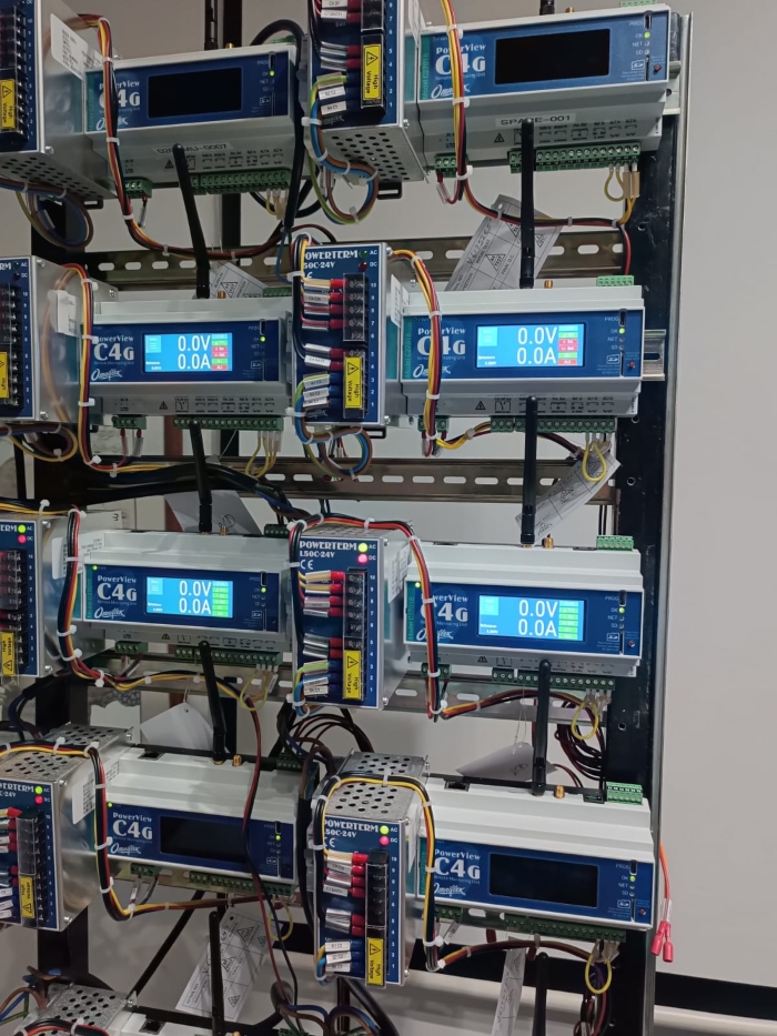
Omniflex, a specialist in cathodic protection monitoring, has developed the PowerView C4 as one such approach. According to the company, the module is designed to connect to existing tap or phase-control T/Rs, allowing operators to add remote monitoring without necessarily replacing the underlying rectifier.
The system can communicate wirelessly with a cloud platform or use Ethernet and serial communications to connect to a local network. It is intended to work with CP infrastructure of different ages without requiring additional signal-conditioning equipment.
For operators with extensive legacy infrastructure, the significance is less about adding another piece of technology and more about extending the usefulness of equipment that is already installed.
Making faults easier to see
One of the potential advantages of continuous monitoring becomes apparent where a single T/R supplies multiple anodes.
Under a conventional arrangement, a failure of one anode may alter the overall current drawn by the system, but the change may not immediately reveal which component is responsible. Engineers may therefore need to investigate individual parts of the installation before identifying the fault.
Continuous monitoring of current and voltage, combined with historical records, can provide a clearer picture of changes in system behaviour.
The objective is not simply to collect more data. It is to turn that data into information that can support maintenance decisions.
A persistent change in operating conditions can trigger an investigation. An abrupt deviation can prompt a faster response. Historical records can also help engineers understand whether a change is an isolated event or part of a longer-term deterioration.
This moves CP management closer to the condition-monitoring model already being adopted across other areas of industrial infrastructure.
Remote control goes beyond monitoring
Remote connectivity can also change what engineers are able to do without travelling to site.
The PowerView C4 is designed to support functions including remote adjustment, automatic potential control and remote CP testing, according to Omniflex. These capabilities can further reduce dependence on physical access to equipment.
That distinction matters for remote infrastructure. Monitoring tells an operator what is happening; remote control can, within the capabilities and safety requirements of the installation, allow an appropriate response without immediately dispatching a technician.
Physical inspection will of course remain necessary. Connected monitoring does not eliminate the need for maintenance personnel, field verification or periodic inspection where these are required by engineering practice or regulation.
It can, however, change when those visits take place and why.
A broader shift in infrastructure maintenance
The move toward remote CP monitoring reflects a wider change taking place across industrial infrastructure.
Much of the world’s critical infrastructure was designed around a maintenance model in which engineers periodically travelled to equipment, took measurements and recorded the results. Digital technologies are gradually making it possible to supplement that model with continuous condition information.
The challenge is particularly pronounced in mature infrastructure. Replacing every legacy component with a modern equivalent is rarely practical. A more realistic approach can be to connect existing assets to new monitoring and communications technologies while retaining equipment that remains technically sound.
For pipeline operators, cathodic protection is a good example of this transition. The physical infrastructure may remain largely unchanged, but the way its condition is observed can evolve significantly.
The longer-term objective is not simply to make CP systems easier to inspect. It is to give asset managers a more complete picture of how corrosion protection is performing between inspections, allowing maintenance resources to be directed towards systems showing evidence of deterioration or abnormal behaviour.
As pipelines and other metallic infrastructure continue to age, that additional visibility could become increasingly valuable. The equipment protecting an asset may have been installed decades ago. The information used to decide whether it is still doing its job does not necessarily have to be.

-
Product on sale
 AWEBook Volume 2Original price was: KShs 3,500.00.KShs 3,000.00Current price is: KShs 3,000.00.